I would like to introduce beginners to CAD, so they can kick-start their learning journey toward what they want from this field.
I have chosen to start from Autodesk's "Fusion 360". It is a great platform with simple interface and a very smart architecture. Also, it is a personal favorite when I require fast generation of a product concept. It is an impressive tool for first-timers.
Tutorial's Objectives:
Simply configuring the work space (Design units, visual style), and saving your work.
Sketching using the tools: (Line, Center Diameter Circle, Trim, Extend).
Creating a model using the tools: (Extrude: new body, cut).
Inspecting the model and measuring lengths, distances, and surface areas.
Step-By-Step illustration:
fig.1: Isometric view with dimensions
- Viewing this body isometrically gives rational pictures of the body from its top and two sides. Dimensions here are given in mm's. We will model this on Fusion 360 as a our first practice.
fig.2: An empty workspace showing the grid isometrically
- Fusion 360's workspace, by default is an isometric view of the drawing grid.
fig.3: The drop down menu where we can choose the preferences.
- On the right top of Fusion 360's window, there is a box with the username. Click on the box, and then click on preferences.
fig.4: Preferences window
- Expand the "Default Units" menu if it is not expanded, click on "Design". From the drop down menu, select "mm".
fig.5: Choosing a visual style from the given options
- This step is optional, as choosing a certain visual style is for convenience. I have chosen to see the body Shaded with Visible Edges only for illustrating. After you created the body, choose between the given options to know the differences and probably know which is for which.
fig.6: Palette
- We toggle sketching by selecting any of the sketching tools, here we choose "Line" by clicking it.
fig.7: Origin (point, coordinates and planes)
- After we clicked on "Line" from the palette (or the drop down menu titled "Sketch"), the Origin planes show up so we can choose the plane on which we will draw our sketch. We choose the top plane.
fig.8: Top View
- The grid animates to bring the top view to the front of the workspace.
- We place the cursor on the origin point and click to place the first point of the line.
fig.9: Sketching
- Hover with the mouse cursor to place the second point of the line. While hovering, you will find two values that change with the point location; the length and the angle.
fig.10: Sketching (entering the line's defining values)
- If you start typing, you will, by default, be changing the length. If you press "tab", you will move the selection to the angle value. Type "48", then "tab", then type "90", then tab. You will find the line locked on the entered values unless changed. Click to accept these parameters and move to the next point.
fig.11: Sketching (loop of lines)
- Same as the previous line but the first point of this line is the second point of the previous, so it is only one point remaining to define this line.
- Type "36", "tab", type "0".
fig.12: Sketching (snapping to useful points)
- Same as the previous point, only this time we will just snap this point to the horizontal origin line like shown in figure and click to confirm.
fig.13: Sketching (closing)
- Last point goes to the first point to close the loop of lines, click to confirm.
sequence of steps
fig.14: Sketching (ending a command)
- right click anywhere after the loop is closed, hover to "Ok" and click to confirm the ending of this tool.
fig.15: Sketching (stop sketch)
- Click on "STOP SKETCH"
fig.16: The cube in the top right corner
- Click the home icon in the top right corner to change the view to the home isometric view.
fig.17: Home view
- We are ready to implement the "Extrude" command.
fig.18: Extrude
- Hover the mouse to the "EXTRUDE" command and click it. If not visible in the palette, look for it in the drop down menu under "CREATE"
fig.19: Extrude
- Select the sketched profile.
fig.20: Extrude
fig.21: Extrude
- Type "18" in the distance field. Make sure that the other selected parameters are the same as the ones in fig.21.
- Click "ok" to confirm your selections.
fig.22: Extrude
fig.23: Changing view
- Click on the highlighted corner of the view cube (top right corner).
fig.24: Selecting a planar face for sketching
- Select the shown face for sketching. Toggle sketching by choosing any tool under "SKETCH".
fig.25: Sketching
- After the planar face was selected and the line tool, the view changed automatically to this view.
- From the origin, drag a line to the center, or type "18", or you can even type in a subtraction form: (36 - 18). ""36" is the original width of the previously sketched profile."
- Hit "enter"!
fig.26: Sketching
- Right click and hover upwards to select "Repeat Line" and click.
fig.27: Sketching
- Draw the line shown in figure.
fig.28: Sketching
fig.29: Sketching (closing the loop)
- Continue until the loop is closed.
fig.30: Sketching (selecting Center Diameter Circle)
- Choose from the "SKETCH" palette (or its drop down menu if not visible in the palette), the Center Diameter Circle tool.
fig.31: Sketching
- Place the cursor on the top left corner of the sketched rectangle and click.
- Drag the mouse cursor (you should be seeing a circle that is expanding or contracting according to the direction of the cursor) to the top right corner of that rectangle.
fig.32: Sketching (trim command)
- From the "SKETCH" palette or its drop down menu, select the "Trim" command.
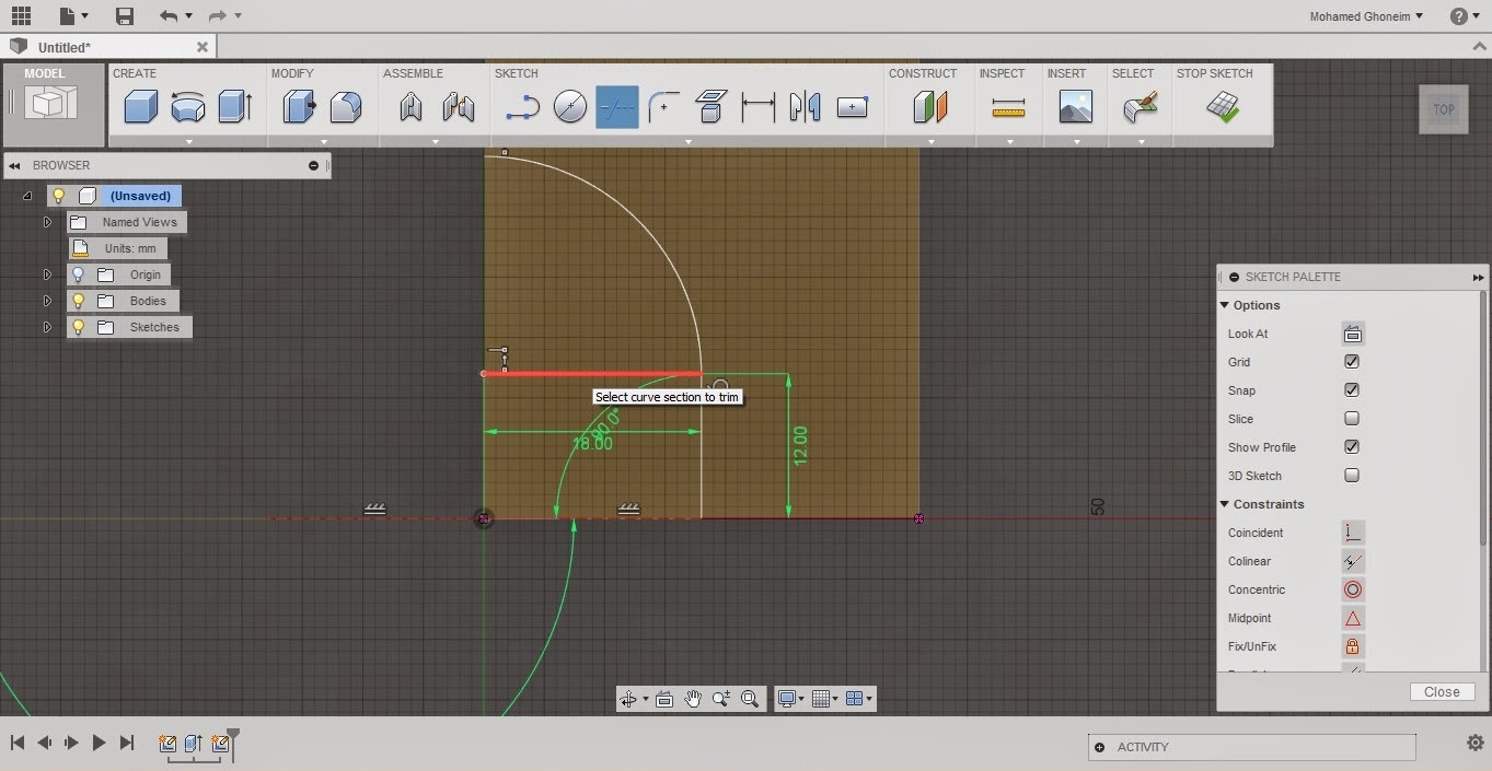
fig.33: Sketching (trimming)
- While the "Trim" command is active, hovering around will turn some entities' color to red. If you click the red entity (lines or curves) it disappears.
- This piece of work, you will do it yourself.
fig.34: Sketching (trimming)
- The trimming is over when only this remains.
- Finish the trim command (right click then what?).
fig.35: Sketching (Extend)
- From the "SKETCH" palette or its drop down menu, select "Extend".
fig.36: Sketching (Extend)
- Hover the cursor to the left bottom vertical segment, and observe the red line shows up.
- Click on the small segment when the red line shows.
fig.37: Sketching
- End the "Extend" command.
fig.38: End of sketch
- End sketching by "STOP SKETCH"
fig.39: Resulting profile
- After you "STOP SKETCH"ed, the view animates to this automatically.
- Hover the mouse cursor to "Extrude" from "CREATE".
fig.40: Cutting the body
- Select the most recently sketched profile.
fig.41: Cut Extrude
- From the drop down menu titled "Operation", select "Cut".
fig.42: Cut Extrude
- From "Extents", select "All". Yes, it gives an error.
- This error is because of the direction the cutter is taking. In this direction, there is no body to cut.
fig.43: Cut Extrude
- Click on "Flip" and the body is now cut.
fig.44: Cut Extrude
- Click "Ok" to finish the "Extrude" command.
fig.45: Resulting Body
- Hover to the highlighted corner of the view cube and click it.
fig.46: Another view
- Now, this view is more relevant compared to the drawing we modeled from.
Inspecting the model.
- To verify that everything we did was right, we need to inspect the model we created.
- Inspecting this model will be by measuring the dimensions we originally modeled from.
fig.47: Inspect
- Hover with the mouse cursor to the "INSPECT" palette and select "Measure".
- Start selecting lines, curves, surfaces to measure and find possible relations.
fig.48: Select to inspect
fig.49: Select to inspect
fig.50: Select to inspect
- Saving your work is crucial in CADing
fig.51: Saving your work
fig.52: Saving your work
fig.53: Saving your work
The end of the introductory tutorial.
I wish it was useful. I hope you have broken the ice with, at least, this CAD software.
More to come.
Check this video